Range Rover Evoque: Cylinder Head
Removal
NOTES:
Some illustrations may show the engine removed for clarity.
Some variation in the illustrations may occur, but the essential information is always correct.
1. Refer to: Battery Tray (414-01 Battery, Mounting and Cables, Removal and Installation).
2. Refer to: Cooling System Draining, Filling and Bleeding (303-03B Engine Cooling - GTDi 2.0L Petrol, General Procedures).
3. Refer to: Camshafts (303-01B Engine - GTDi 2.0L Petrol, Removal and Installation).
4. Refer to: Intake Manifold (303-01B Engine - GTDi 2.0L Petrol, Removal and Installation).
5.

6. Remove the special tool.

7.

8.

9.

10.

11. CAUTION: Using suitable tie straps, make sure the turbocharger assembly is secure.

12. CAUTIONS:
Make sure that all openings are sealed. Use new blanking caps.
Be prepared to collect escaping coolant.
- Carefully remove and discard the oil seal.

13.

14.

15.

16.
- Remove and discard the cylinder head gasket.

Installation
1.
- Clean the components mating faces.

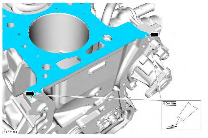
2. CAUTION: Apply sealant WSE-M4G323-A6 in a 5-7mm diameter on both cylinder head gasket notches as shown. The cylinder head and engine front cover must be installed and tightened within 30 minutes of sealant application.
3.
- Clean the component mating faces.

4. CAUTION: Cylinder head bolts may be reused a maximum of two times only.
NOTE: Tighten the bolts in the indicated sequence.
Torque:
- Stage 1: 7 Nm
- Stage 2: 15 Nm
- Stage 3: 55 Nm
- Stage 4: 90
