Range Rover Evoque: Exhaust System
Exhaust System - GTDi 2.0L Petrol
Lubricants, Fluids, Sealers and Adhesives

* Apply to area around sensor threads prior to attempting to remove sensor
General Specification

Torque Specifications

** It is not appropriate to either fit or remove these fixings using air
tools due to a risk of cold welding/snapping.
*** Apply anti-seize lubricant to threads of sensor - See Lubricants
Exhaust System - Component Location
COMPONENT LOCATION
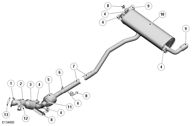
- Exhaust mounting flange to turbocharger
- Flexible coupling
- Pre-catalyst
- Rubber mountings (6 off)
- Catalyst
- Clamp
- Center pipe
- Exhaust hanger bracket
- Tail pipe finisher (2 off)
- Rear silencer
- Metal gasket
- Manifold support bracket
- Gasket
Exhaust System - Overview
OVERVIEW
The GTDi exhaust system is manufactured from stainless steel tubing. It is bolted to the exhaust manifold and is attached to the underside of the vehicle body with 6 rubber mountings, which are located on hanger bars that are welded to the system. The rubber mountings locate on adjacent hanger brackets which are bolted or welded to the underside of the vehicle body and sub-frames.
Exhaust System - System Operation and Component Description
System Operation
OPERATION
For detailed information on the HO2S (heated oxygen sensor)'s, refer to Electronic Engine Controls.
Component Description
DESCRIPTION
The exhaust system comprises three separate sections; a front section including a 0.8 liter ceramic pre-catalyst, a center section incorporating a 1.50 liter ceramic catalyst and a rear section comprising a rear pipe and silencer assembly.
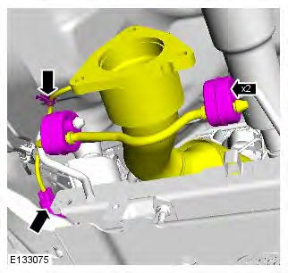
The front section has an inlet flange which mates with the turbocharger outlet. The flange is sealed to the turbocharger with a gasket and secured with three bolts which screw into the turbocharger housing. An elbow from the flange is connected to a flexible coupling. The elbow contains a threaded boss for the installation of the front (upstream) HO2S. A bracket welded to the elbow allows for the attachment of a second bracket which secures the front section to the Power Transfer Unit (PTU). The flexible coupling is connected to the pre-catalyst which in turn is connected by a curved pipe to a flange which mates with the center section and the main catalyst. The curved pipe contains a threaded boss for the installation of the rear (downstream) HO2S. A hanger bar with two rubber mountings is connected to a common bracket, which in turn bolts to the rear of the front sub-frame to support the system.
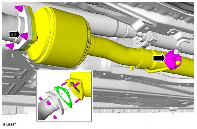
The center section has a flange which connects to the front section flange and is sealed with a metal gasket and secured with three studs and nuts. The flange is connected to the main catalyst. From the catalyst a short section of pipe connects to the rear section.
The rear section has a long pipe which is secured to the center section with a clamp. A hanger bar, mounting rubber and bracket secure the forward end of the pipe to the vehicle body. The pipe is routed in a central position under the vehicle, with a slight deviation around the rear differential, where it joins with the rear silencer. The rear silencer is supported by three rubber mountings; two are welded to the rear subframe and the third is attached to a bracket bolted to the vehicle body. The 28 liter rear silencer has an outlet pipe at each end. Each pipe is fitted with a stainless steel finisher.
Catalytic Converter
Removal
WARNING: Observe due care when working near a hot exhaust system.
NOTE: Removal steps in this procedure may contain installation details.
1. Disconnect the battery ground cable.
Refer to: Specifications (414-01 Battery, Mounting and Cables, Specifications).
2. WARNING: Make sure to support the vehicle with axle stands. Raise and support the vehicle.
3. Refer to: Engine Cover - GTDi 2.0L Petrol (501-05 Interior Trim and Ornamentation, Removal and Installation).
4. Refer to: Battery Tray (414-01 Battery, Mounting and Cables, Removal and Installation).
5.
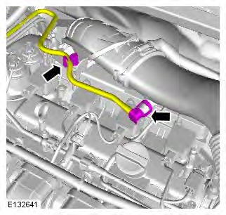
6. Torque:
- Clamp 3.5 Nm
- Bolt 8 Nm
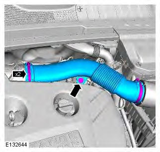
7.
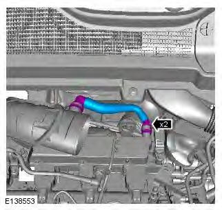
8. Torque:
- M6 10 Nm
- M10 45 Nm
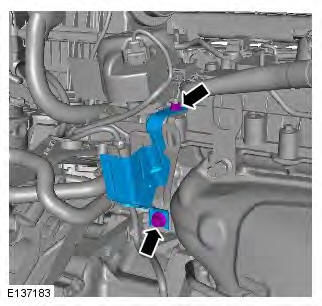
9.
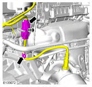
10.
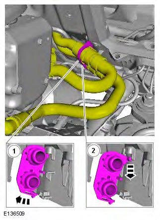
11. Torque: 12 Nm
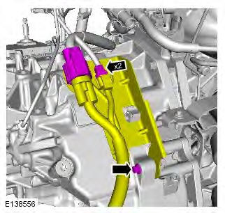
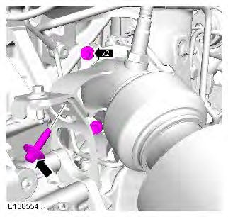
12. CAUTION: Loosen the lower retaining bolt no more than 5 turns (do not remove the retaining bolt). This will aid installation of the catalytic converter.
Torque: 24 Nm
13. CAUTION: Secure with cable ties.
Torque: 24 Nm
14.
15. Torque: 24 Nm
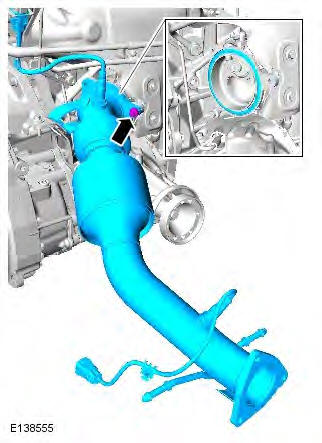
16. NOTE: Do not disassemble further if the component is removed for access only.
Torque: 47 Nm
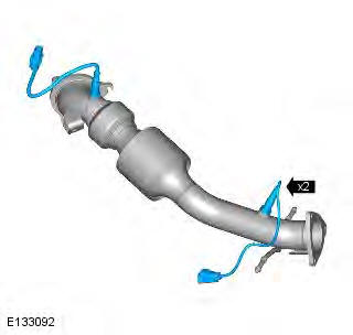
Installation
1. To install, reverse the removal procedure.
Exhaust System
Removal
WARNING: Observe due care when working near a hot exhaust system.
NOTE: Removal steps in this procedure may contain installation details.
1. WARNING: Make sure to support the vehicle with axle stands. Raise and support the vehicle.
2.
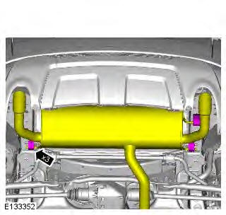
3. WARNING: This step requires the aid of another technician. Torque: 55 Nm
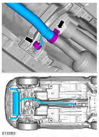
Installation
1. CAUTION: Make sure that the component aligns with the installation mark.
To install, reverse the removal procedure.
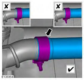
Exhaust System
Principles of Operation
For a detailed description of the exhaust system, refer to the relevant Description and Operation section in the workshop manual. REFER to: (309-00D)
Inspection and Verification
CAUTION: Diagnosis by substitution from a donor vehicle is NOT acceptable. Substitution of control modules does not guarantee confirmation of a fault, and may also cause additional faults in the vehicle being tested and/or the donor vehicle.
1. Verify the customer concern.
2. Visually inspect for system integrity and obvious signs of mechanical damage.
Visual Inspection
- Leaks
- Restrictions or blockages
- Metal fatigue
- Pipes, mufflers and catalytic converters
- Joints or gaskets
- Mountings
- Clearance around components
3. If an obvious cause for an observed or reported concern is found, correct the cause (if possible) before proceeding to the next step.
4. If the cause is not visually evident, verify the symptom and refer to the Symptom Chart.
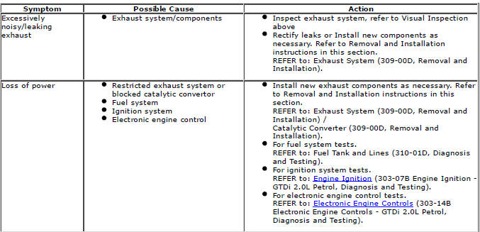
Symptom Chart
DTC Index
For a complete list of all Diagnostic Trouble Codes (DTCs) that could be logged on this vehicle.

