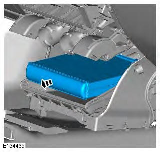
Range Rover Evoque: Desiccant Bag GTDi 2.0L Petrol
Removal
NOTE: Removal steps in this procedure may contain installation details.
1. WARNING: Make sure to support the vehicle with axle stands. Raise and support the vehicle.
2. Refer to: Condenser - GTDi 2.0L Petrol (412-01 Climate Control, Removal and Installation).
3. Torque: 11 Nm

Installation
1. To install, reverse the removal procedure.
Desiccant Bag TD4 2.2L Diesel
Removal
NOTE: Removal steps in this procedure may contain installation details.
1. WARNING: Make sure to support the vehicle with axle stands.
Raise and support the vehicle.
2. Refer to: Condenser - TD4 2.2L Diesel (412-01 Climate Control, Removal and Installation).
3. Torque: 11 Nm

Installation
1. To install, reverse the removal procedure.
Heater Core GTDi 2.0L Petrol
Removal
NOTE: Removal steps in this procedure may contain installation details.
1. Disconnect the battery ground cable.
Refer to: Specifications (414-01 Battery, Mounting and Cables, Specifications).
2. Refer to: Cooling System Partial Draining, Filling and Bleeding (303-03B Engine Cooling - GTDi 2.0L Petrol, General Procedures).
3. Refer to: Electric Booster Heater (412-02 Auxiliary Climate Control, Removal and Installation).
4. CAUTION: Be prepared to collect escaping coolant.

5.

6. CAUTION: Be prepared to collect escaping coolant.

Installation
1. To install, reverse the removal procedure.
Thermostatic Expansion Valve GTDi 2.0L Petrol
Removal
NOTE: Removal steps in this procedure may contain installation details.
1. Disconnect the battery ground cable.
Refer to: Specifications (414-01 Battery, Mounting and Cables, Specifications).
2. Refer to: Air Conditioning (A/C) System Recovery, Evacuation and Charging - GTDi 2.0L Petrol (412-00 Climate Control System - General Information, General Procedures).
3. Refer to: Engine Control Module (ECM) (303-14B Electronic Engine Controls - GTDi 2.0L Petrol, Removal and Installation).
4. CAUTIONS: Make sure that all openings are sealed. Use new blanking caps.
Lubricate the new seals with clean refrigerant oil.
NOTE: Install new O-ring seals.
Torque: 9 Nm

5. Torque: 4 Nm

Installation
1. To install, reverse the removal procedure.
Blower Motor Resistor RHD AWD/RHD FWD
Removal
NOTE: Removal steps in this procedure may contain installation details.
1. Disconnect the battery ground cable.
Refer to: Specifications (414-01 Battery, Mounting and Cables, Specifications).
2. NOTE: LHD illustration shown, RHD is similar.

3. NOTE: LHD illustration shown, RHD is similar.

4.

Installation
1. To install, reverse the removal procedure.
Footwell Vent/Duct Blend Door Actuator RHD AWD/RHD FWD
Removal
NOTE: Removal steps in this procedure may contain installation details.
1. Disconnect the battery ground cable.
Refer to: Specifications (414-01 Battery, Mounting and Cables, Specifications).
2. Refer to: Glove Compartment (501-12 Instrument Panel and Console, Removal and Installation).
3.

4.

Installation
1. To install, reverse the removal procedure.
2. If a new component has been installed, configure using Land Rover approved diagnostic equipment.
Temperature Blend Door Actuator LH RHD AWD/RHD FWD
Removal
NOTE: Removal steps in this procedure may contain installation details.
1. Disconnect the battery ground cable.
Refer to: Specifications (414-01 Battery, Mounting and Cables, Specifications).
2. Refer to: Glove Compartment (501-12 Instrument Panel and Console, Removal and Installation).
3.

4.

Installation
1. To install, reverse the removal procedure.
2. If a new component has been installed, configure using Land Rover approved diagnostic equipment.
Defrost Vent/Register Blend Door Actuator RHD AWD/RHD FWD
Removal
NOTE: Removal steps in this procedure may contain installation details.
1. Make the SRS system safe.
Refer to: Standard Workshop Practices (100-00 General Information, Description and Operation).
2. Refer to: Steering Column (211-04 Steering Column, Removal and Installation).
3.

Installation
1. To install, reverse the removal procedure.
2. If a new component has been installed, configure using Land Rover approved diagnostic equipment.

