Range Rover Evoque: Central Junction Box (CJB)

Range Rover Evoque. CAUTIONS CAUTIONS:

Diagnosis by substitution from a donor vehicle is NOT acceptable. Substitution of control modules does not guarantee confirmation of a fault, and may also cause additional faults in the vehicle being tested and/or the donor vehicle

When probing connectors to take measurements in the course of the pinpoint tests, use the adaptor kit, part number 3548-1358-00

Range Rover Evoque. NOTES NOTES:

If the control module or a component is suspect and the vehicle remains under manufacturer warranty, refer to the warranty policy and procedures manual (section B1.2), or determine if any prior approval programme is in operation, prior to the installation of a new module/component

Generic scan tools may not read the codes listed, or may read only 5-digit codes. Match the 5 digits from the scan tool to the first 5 digits of the 7-digit code listed to identify the fault (the last 2 digits give extra information read by the manufacturer-approved diagnostic system)

When performing voltage or resistance tests, always use a digital multimeter accurate to three decimal places and with a current calibration certificate. When testing resistance, always take the resistance of the digital multimeter leads into account

Check and rectify basic faults before beginning diagnostic routines involving pinpoint tests

Inspect connectors for signs of water ingress, and pins for damage and/or corrosion

If diagnostic trouble codes are recorded and, after performing the pinpoint tests, a fault is not present, an intermittent concern may be the cause. Always check for loose connections and corroded terminals

Where an 'on demand self-test' is referred to, this can be accessed via the 'diagnostic trouble code monitor' tab on the manufacturers approved diagnostic system

Check DDW for open campaigns. Refer to the corresponding bulletins and SSMs which may be valid for the specific customer complaint and carry out the recommendations as required

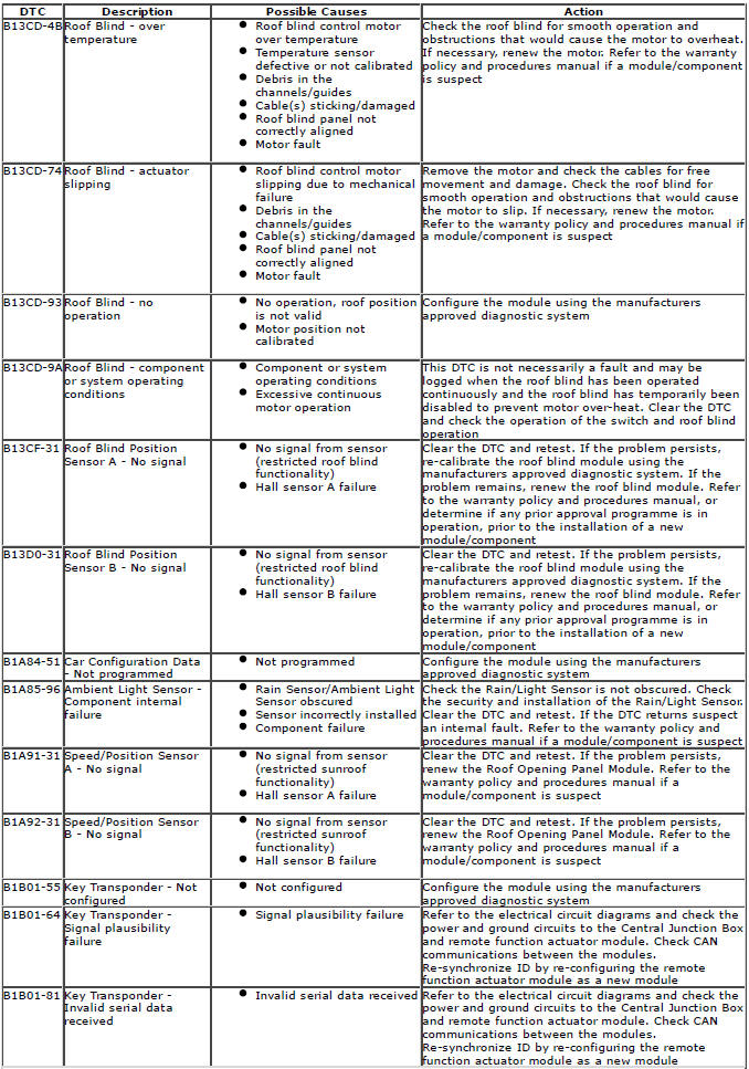
The table below lists all diagnostic trouble codes (DTCs) that could be logged in the central junction box, for additional information refer to the relevant Description and Operation section.

For additional information, refer to: Communications Network (418-00 Module Communications Network, Description and Operation) / Communications Network (418-00 Module Communications Network, Description and Operation).

Range Rover Evoque. Diagnostic Trouble Code (DTC) Index DTC

Range Rover Evoque. Diagnostic Trouble Code (DTC) Index DTC

Range Rover Evoque. Diagnostic Trouble Code (DTC) Index DTC

Range Rover Evoque. Diagnostic Trouble Code (DTC) Index DTC

Range Rover Evoque. Diagnostic Trouble Code (DTC) Index DTC

Range Rover Evoque. Diagnostic Trouble Code (DTC) Index DTC

Range Rover Evoque. Diagnostic Trouble Code (DTC) Index DTC

Range Rover Evoque. Diagnostic Trouble Code (DTC) Index DTC

Range Rover Evoque. Diagnostic Trouble Code (DTC) Index DTC

Range Rover Evoque. Diagnostic Trouble Code (DTC) Index DTC

Range Rover Evoque. Diagnostic Trouble Code (DTC) Index DTC

Range Rover Evoque. Diagnostic Trouble Code (DTC) Index DTC

Range Rover Evoque. Diagnostic Trouble Code (DTC) Index DTC

Range Rover Evoque. Diagnostic Trouble Code (DTC) Index DTC

Range Rover Evoque. Diagnostic Trouble Code (DTC) Index DTC

Range Rover Evoque. Diagnostic Trouble Code (DTC) Index DTC

Range Rover Evoque. Diagnostic Trouble Code (DTC) Index DTC

Range Rover Evoque. Diagnostic Trouble Code (DTC) Index DTC

Range Rover Evoque. Diagnostic Trouble Code (DTC) Index DTC

READ NEXT:

 Digital Audio Broadcast Module (DABM)

CAUTION: Diagnosis by substitution from a donor vehicle is NOT acceptable. Substitution of control modules does not guarantee confirmation of a fault, and may also cause additional faults in the v

 Gearshift Module (GSM)

  CAUTIONS: Diagnosis by substitution from a donor vehicle is NOT acceptable. Substitution of control modules does not guarantee confirmation of a fault, and may also cause additional faults in

 Headlamp Leveling Control Module (HLCM)

Headlamp Control Module (HCM)  CAUTION: Diagnosis by substitution from a donor vehicle is NOT acceptable. Substitution of control modules does not guarantee confirmation of a fault, and may als

SEE MORE:

 Control Diagram, System Operation

Control Diagram NOTE: A = Hardwired; D = High speed CAN (controller area network) bus; O = LIN (local interconnect network) bus Battery BJB (battery junction box) Front height sensor Rear height sensor Headlamp leveling control module Front right fog lamp Front left fog lamp Left side rep

 Rear Suspension FWD

Component Location Stabilizer link RH (right-hand) spring and damper assembly Stabilizer bar LH (left-hand) spring and damper assembly Wheel knuckle Stub axle and locknut Hub Longitudinal link Rear transverse link Front transverse link Front Wheel Drive (FWD) Rear Subframe Overview The

© 2011-2024 Copyright www.rrevoque.org