Range Rover Evoque: Rear Lower Arm AWD
Special Tool(s)
 205-857
Remover, Halfshaft
Removal
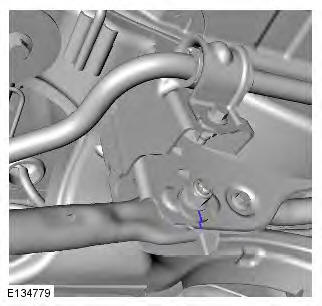
CAUTION: LH illustration shown, RH is similar.
NOTE: Some variation in the illustrations may occur, but the essential information is always correct.
1. WARNING: Make sure to support the vehicle with axle stands. Raise and support the vehicle.
2. Refer to: Wheel and Tire (204-04 Wheels and Tires, Removal and Installation).
3. CAUTION: Discard the nut.

4.

5. CAUTION: Note the fitted position of the special washer.

6.

7.

8. CAUTIONS:
Make sure that the driveshaft is supported with suitable retaining straps.
Do not use a hammer to detach the halfshaft from the hub assembly, failure to follow this instruction may result in damage to the halfshaft.
Special Tool(s): 205-857

9.

10. NOTE: Do not disassemble further if the component is removed for access only.

Installation
1. NOTE: This step is only required if previously removed.

2. CAUTION: Only tighten the nut and bolt finger-tight at this stage.

3.

4. CAUTION: Only tighten the nuts and bolts finger tight at this stage.

5. CAUTION: Only tighten the nut and bolt finger-tight at this stage.

6. CAUTION: Nuts and bolts must be tightened with the weight of the vehicle on the suspension.
Support weight of vehicle on a jack at the rear hub.
7.

8. CAUTION: Note the fitted position of the special washer.
9. Torque: 175 Nm

10. Torque: 175 Nm

11. Torque: 270 Nm

12. Refer to: Wheel and Tire (204-04 Wheels and Tires, Removal and Installation).
13. Check and if necessary, adjust the rear wheel alignment
Trailing Arm
Removal
NOTE: Some variation in the illustrations may occur, but the essential information is always correct.
1. WARNING: Make sure to support the vehicle with axle stands. Raise and support the vehicle.
2. Refer to: Wheel and Tire (204-04 Wheels and Tires, Removal and Installation).
3. CAUTION: Make sure the bushing(s) or isolator(s), are not strained or left unsupported during this procedure.

4.

Installation
1. CAUTION: Only tighten the nut and bolt finger-tight at this stage.

2. CAUTION: Only tighten the nut and bolt finger-tight at this stage.

3. Torque: 110 Nm

4. CAUTION: Nuts and bolts must be tightened with the weight of the vehicle on the suspension. Support weight of vehicle on a jack at the rear hub.
5. Torque: 270 Nm

6. Refer to: Wheel and Tire (204-04 Wheels and Tires, Removal and Installation).
7. Check and if necessary, adjust the rear wheel alignment
READ NEXT:
 Rear Stabilizer Bar
Removal
NOTES:
Some variation in the illustrations may occur, but the essential
information is always correct.
Removal steps in this procedure may contain installation details.
1. WARNING: Make sure
Wheel Knuckle
Special Tool(s)
205-857
Remover, Halfshaft
JLR-204-804
Lever, Wheel Knuckle
Removal
CAUTIONS:
Nuts and bolts must be tightened with the weight of the vehicle on the
suspension.
Do not allow halfshaf
Rear Shock Absorber Vehicles Without: Dynamic
Suspension
General Equipment
Suspension Spring Compressor
Vise
Removal
WARNINGS:
Make sure the spring compressor Safe Working Load (SWL) meets or exceeds
the spring rating quoted in the
Specifcations sectio
SEE MORE:
Tyre pressure monitoring (TPM) system
The TPM system provides a low
pressure warning and does not
re-inflate your tyres. Tyre pressures
should be checked regularly using an
accurate pressure gauge when cold.
The TPM system can NOT register
damage to a tyre. Regularly check the
condition of your tyres, especially if
the vehicle
Changing a bulb
If the lighting has just
been switched
off, give the bulbs time to cool.
Handling them when hot may cause
personal injury.
Always replace bulbs with
the correct
type and specification. If you are in any
doubt contact your Land Rover
Dealer/Authorised Repairer for advice.
See 199, BULB
