Range Rover Evoque: Rear Wheel Bearing
Special Tool(s)
 204-250
Wheel bearing install and removal tool
 204-305
Remover, Wheel Bearing
 204-726
Remover/Installer, Wheel Bearing
 JLR-204-806
Support Tool, Wheel Knuckle
 JLR-204-809
Installer, Rear Wheel Bearing
 JLR-204-810
Installer, Rear Wheel Bearing
General Equipment
- Copper Hammer
- Hydraulic press
- Punch
- Vise
Removal
1. WARNING: Make sure to support the vehicle with axle stands. Raise and support the vehicle.
2. Refer to: Wheel Knuckle (204-02 Rear Suspension, Removal and Installation).
3.
- Special Tool(s): JLR-204-806
- Special Tool(s): 204-726
- General Equipment: Hydraulic press

4.
- General Equipment: Vise
- General Equipment: Copper Hammer
- General Equipment: Punch

5.
- Special Tool(s): 204-305
- General Equipment: Hydraulic press

6. Clean all the mating faces and reusable parts thoroughly and check for damage.

7.

8. NOTE: Note the orientation of the component prior to removal.
- Special Tool(s): 204-250
- General Equipment: Hydraulic press

Installation
1. CAUTION: Make sure that the area around the component is clean and free of foreign material.
Special Tool(s): JLR-204-809

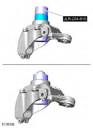
2. NOTE: Make sure that the component is installed to the noted removal position.
- Special Tool(s): JLR-204-810
- General Equipment: Hydraulic press
3.

4.
- Special Tool(s): 204-726
- General Equipment: Hydraulic press

5. Refer to: Wheel Knuckle (204-02 Rear Suspension, Removal and Installation).
READ NEXT:
 Front Lower Arm
Removal
NOTES:
Some variation in the illustrations may occur, but the essential
information is always correct.
Front wheel drive transmission illustrations shown, all wheel wheel drive
transmission
Rear Lower Arm AWD
Special Tool(s)
205-857
Remover, Halfshaft
Removal
CAUTION: LH illustration shown, RH is similar.
NOTE: Some variation in the illustrations may occur, but the essential
information is always correct.
Rear Stabilizer Bar
Removal
NOTES:
Some variation in the illustrations may occur, but the essential
information is always correct.
Removal steps in this procedure may contain installation details.
1. WARNING: Make sure
SEE MORE:
Ride and Handling Optimization
Ride and Handling Optimization AWD
COMPONENT LOCATION
Terrain Response switchpack and control module
OVERVIEW
The Terrain Response system allows the driver to select a program which aims
to provide the optimum settings for
traction and performance for the prevailing terrain conditions. The sys
Instrument Cluster
Instrument Cluster - Component Location
COMPONENT LOCATION
Instrument Cluster - Overview
OVERVIEW
The instrument cluster comprises two analogue gages for the speedometer and
the tachometer and a 5 inch Thin Film
Transistor (TFT) display for driver information.
The analogue gages are electronicall
