Range Rover Evoque: Rear Seat Cushion Cover
Removal
NOTE: Removal steps in this procedure may contain installation details.
1. Prior to carrying out the step by step procedure below, Steps 2 and 3 must be followed for knowledge on how to correctly install and care for the seat cover.
2.

3.

4. If required, follow the steps below to carry out the removal and installation procedure.
5. Refer to: Rear Seat Cushion (501-10 Seating, Removal and Installation).
6.

7. NOTE: Make sure that new hog rings are installed.
Installation
1. NOTES:
If a replacement rear seat backrest cover is to be installed, cut out holes for the head restraint guide tubes and center safety belt trim panel. Use the existing rear seat backrest cover as a template. This also applies to the backrest squab foam.
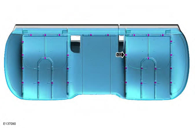
Use hog ring pliers to close the hog rings. Do not use any other tool. The hog rings must be closed to overlap as illustrated.
Make sure that new hog rings are installed.

2. NOTE: Make sure that the hogrings are installed in the sequence shown.

3. NOTE: Make sure that the hogrings are installed in the sequence shown.

4. To install, reverse the removal procedure.
READ NEXT:
 Front Seat Backrest Heater Mat
Removal
WARNINGS:
To avoid accidental deployment and possible personal injury, the backup
power supply must be depleted before
repairing or replacing any air bag supplemental restraint system (SRS)
Rear Seat Backrest Cover 3-Door
Removal
NOTES:
This procedure covers the removal and installation of both rear seat
backrests and the LH rear seat backrest cover.
The RH rear seat backrest cover is similar. All notes and cautions
Front Seat Track
Removal
NOTE: Removal steps in this procedure may contain installation details.
All vehicles
1. Disconnect the battery ground cable.
Refer to: Specifications (414-01 Battery, Mounting and Cables,
Spe
SEE MORE:
Front Side Member Section
Removal
NOTES:
The front side member is manufactured from RP260 and DP600.
The front side member section is cut from the front side member and is
manufactured from RP260.
This procedure is written for the LH front side member section replacement, the
LH and RH front side member sections differ i
Engine Timing
Special Tool(s)
303-1565
Locking Tool, Camshaft
308-511
Installer, Transmission Output Shaft Seal
JLR-303-1594
Locking Tool, Driveplate
JLR-303-748
Locking Tool, Crankshaft
Activation
1.
2. Install the special tool.
Special Tool(s): JLR-303-748
3. Rotate the engine clockwise until the crankshaft
