Range Rover Evoque: Overhead Console
Removal
NOTE: Removal steps in this procedure may contain installation details.
1. CAUTION: Take extra care not to damage the edges of the component.

2.

3. NOTE: Do not disassemble further if the component is removed for access only.

4. CAUTION: Take extra care not to damage the wiring harnesses.
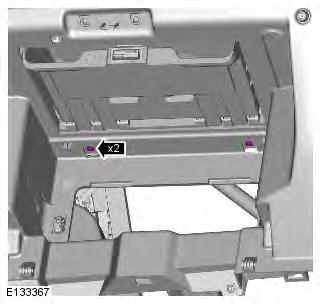
Take precautions to avoid any electrostatic charging, which could damage this comopnent.

5.

6. CAUTION: Take extra care not to damage the wiring harnesses.

7.

8.

Installation
1. CAUTION: Take extra care not to damage the wiring harnesses.
NOTE: If installing a new overhead console, make sure the original blanking plugs are installed to the new component.
To install, reverse the removal procedure.

Glove Compartment
Removal
NOTE: Removal steps in this procedure may contain installation details.
1.

2.

3.

4. NOTES:
Left-hand shown, right-hand similar.
The step must be carried out on both sides.

5.

6. Torque: 4 Nm

7.

8.

9. NOTE: Glove compartment shown removed for clarity.
10. Torque: 6 Nm

Installation
1. To install, reverse the removal procedure.
READ NEXT:
 Floor Console Upper Section
Removal
NOTE: Removal steps in this procedure may contain installation details.
All vehicles
1. CAUTION: The procedure must be carried out on
both sides.
NOTE: LH illustration shown, RH is similar.
T
Locks, Latches and Entry Systems
Principle of Operation
For a detailed description of the locks, latches and entry systems and
operation, refer to the relevant Description and
Operation section of the workshop manual REFER to: Handl
SEE MORE:
Rear Quarter Trim Panel
Removal
NOTE: Removal steps in this procedure may contain installation details.
1. Refer to: Rear Seat Cushion (501-10 Seating, Removal and
Installation).
2. Refer to: Loadspace Trim Panel (501-05 Interior Trim and
Ornamentation, Removal and Installation).
3.
4.
5.
6. CAUTION: Discard the bolt.
Transmission Control Module (TCM), Gear Shift Module (GSM)
TRANSMISSION CONTROL MODULE (TCM)
TCM
Neutral 'N' position
Park 'P' position
Position sensor/manual shaft
Electrical connector
The TCM is located on the top of the transmission casing and is connected on
the high speed CAN (controller area network)
bus to send and receive information to and
