Range Rover Evoque: Cylinder Head
Removal
NOTES:
Some illustrations may show the engine removed for clarity.
Some variation in the illustrations may occur, but the essential information is always correct.
1. Refer to: Battery Tray (414-01 Battery, Mounting and Cables, Removal and Installation).
2. Refer to: Cooling System Draining, Filling and Bleeding (303-03B Engine Cooling - GTDi 2.0L Petrol, General Procedures).
3. Refer to: Camshafts (303-01B Engine - GTDi 2.0L Petrol, Removal and Installation).
4. Refer to: Intake Manifold (303-01B Engine - GTDi 2.0L Petrol, Removal and Installation).
5.

6. Remove the special tool.

7.

8.

9.

10.

11. CAUTION: Using suitable tie straps, make sure the turbocharger assembly is secure.

12. CAUTIONS:
Make sure that all openings are sealed. Use new blanking caps.
Be prepared to collect escaping coolant.
- Carefully remove and discard the oil seal.

13.

14.

15.

16.
- Remove and discard the cylinder head gasket.

Installation
1.
- Clean the components mating faces.

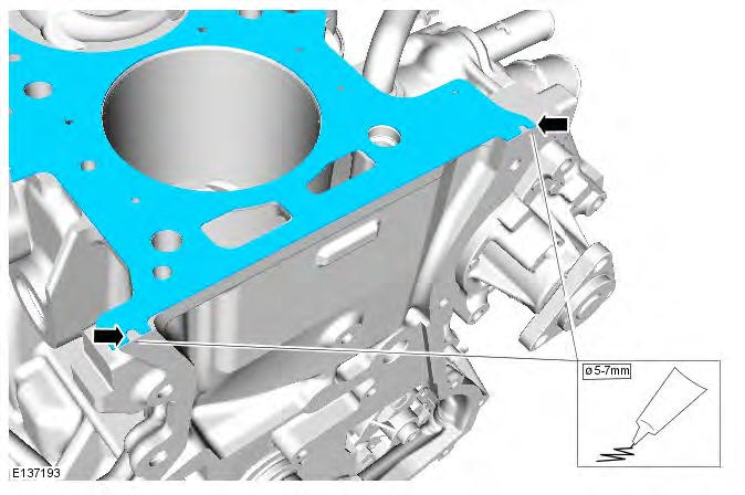
2. CAUTION: Apply sealant WSE-M4G323-A6 in a 5-7mm diameter on both cylinder head gasket notches as shown. The cylinder head and engine front cover must be installed and tightened within 30 minutes of sealant application.
3.
- Clean the component mating faces.

4. CAUTION: Cylinder head bolts may be reused a maximum of two times only.
NOTE: Tighten the bolts in the indicated sequence.
Torque:
- Stage 1: 7 Nm
- Stage 2: 15 Nm
- Stage 3: 55 Nm
- Stage 4: 90
READ NEXT:
 Engine Mount LH/RH
Engine Mount LH
Removal
NOTES:
Removal steps in this procedure may contain installation details.
Some variation in the illustrations may occur, but the essential information is
always correct.
1. Di
Intake Manifold
Removal
NOTES:
Removal steps in this procedure may contain installation details.
Some illustrations may show the engine removed for clarity.
1. WARNING: Make sure to support the vehicle with axle sta
Oil Cooler
Removal
NOTE: Removal steps in this procedure may contain installation details.
1. WARNING: Make sure to support the vehicle with axle stands.
Raise and support the vehicle.
2. Disconnect the battery
SEE MORE:
Tyre change
Valve stem seal, washer, nut,
valve core
and cap should be replaced at every tyre
change. Valve stem seal, washer and
nut must be replaced if valve retention
nut is loosened. Sensor units and nuts
must be refitted using correct torque
figures and associated profile. Damage
to the vehicle m
Battery and Cables AWD
Component
Location
COMPONENT LOCATION - SHEET 1 OF 2 - DW12c
CJB (central junction box)
ECM (engine control module)
RJB (rear junction box)
Battery
BJB (battery junction box)
Starter motor
Generator
COMPONENT LOCATION - SHEET 2 OF 2 - GTDi
CJB
ECM
RJB
Battery
BJB
Starter motor
Gen
